Lesson reading
live
50 min
Start with the lesson question, connect the representations, and test the model with evidence.
Inspect the opening phenomenon
Predict what changes, then name the evidence.
Apply in the lab
Name the evidence before reading the answer.
Read only what helps
Then use the lab and recall check.
More when needed
Transcript and resources stay available below.
Course progress
Position, Orientation, and Coordinate Frames
Decision challenge
Use the opening example to make a prediction, identify evidence, and explain which model supports it.
Predict how one physical point can have two correct coordinate tuples.
Before
Predict how one physical point can have two correct coordinate tuples.
During
Track the rotation, translation, frame names, and time.
After
Name the four facts needed before comparing poses.
Lesson reading
live
50 min
Video script
draft
Transcript fallback
available
courses/ai-robotics/modules/03-motion-frames-and-kinematics/lessons/01-position-orientation-and-coordinate-frames/video-transcript.md
Transform the Same Point Between Frames
draft
25 min
Mastery check
live
6 questions / 10 min
# Video Transcript Can the same physical point have two correct coordinates? Yes—if the coordinates use different frames. A robot pose needs position, orientation, a named frame, and time. Without those, the numbers are incomplete. The robot base is at map two, one, turned ninety degrees. A point one metre forward is base one, zero. Rotate, then translate: in the map, it is two, two. Robots connect map, odom, base link, sensor, and tool frames. Tf2 tracks those transforms over time. Quick check: before comparing two points, what four facts do you need? Position, orientation, frame, and time. Learn the full lesson free on EduQuest.
Reading lab
Connect the lesson's words, diagrams, graphs, evidence, and equations.
Opening challenge: Can the same physical point have two different—but equally correct—coordinates?
A coordinate tuple is incomplete until you know its reference frame. For moving robots, time matters too. A decision-ready pose answers four questions:
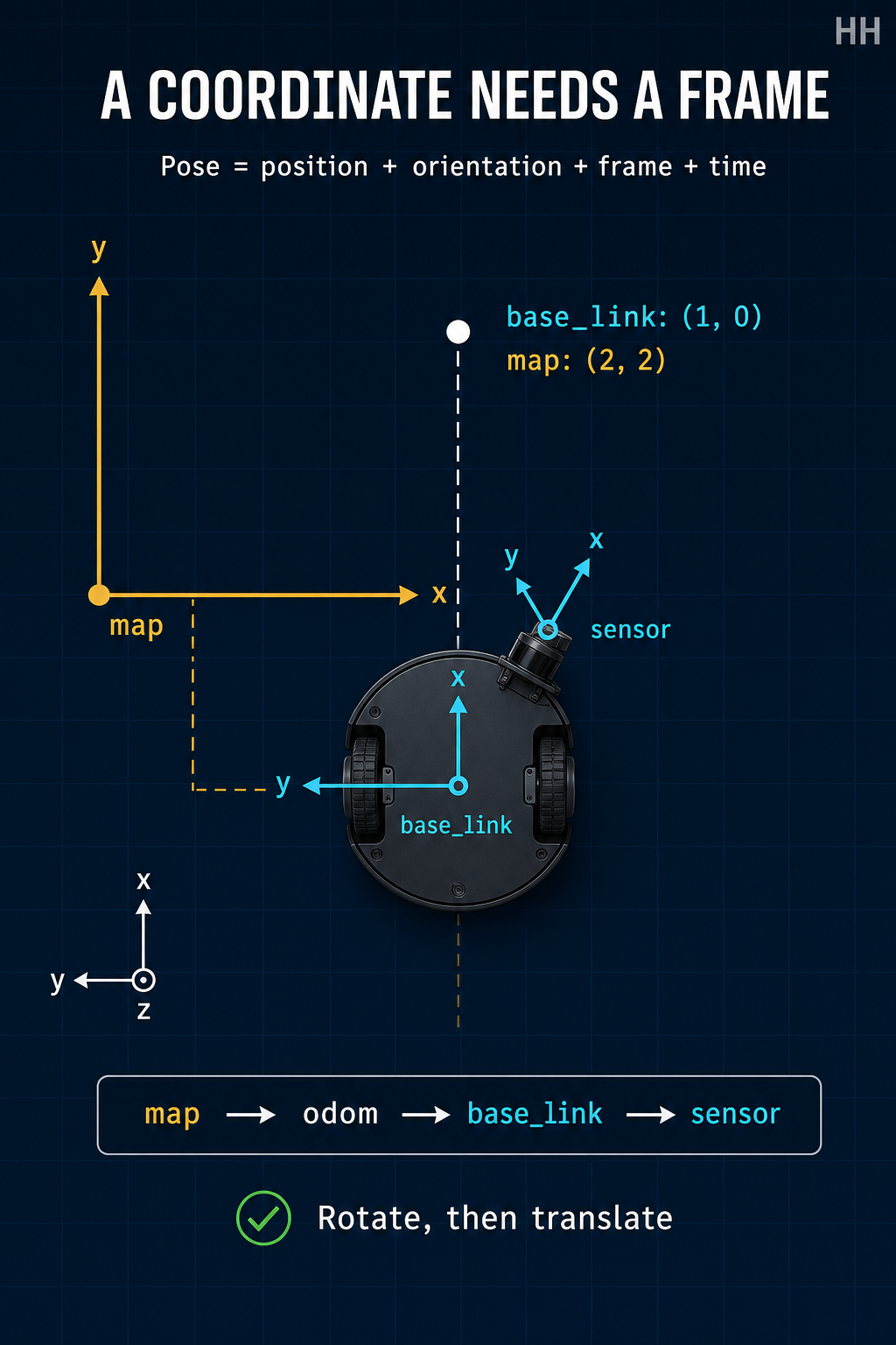
ROS standard conventions use right-handed frames. For a body frame, the common convention is forward, left, and up. A point at (1, 0, 0) in base_link is therefore one metre ahead of the robot—not one metre east in the map.
Position locates a point. Orientation describes how axes are rotated. Together they form a pose. ROS geometry_msgs/Pose contains a Point position and Quaternion orientation; stamped variants add a frame identifier and time through a header.
Roll, pitch, and yaw are intuitive, but rotation order and axis convention must be stated. Euler-angle representations can become singular. Unit quaternions compose and interpolate rotations without that singularity, but their four components are not four angles, they must be normalized, and and encode the same rotation.
Suppose the robot base is at map position with yaw . A target is one metre forward in base_link, so:
Rotate it by :
Then add the base translation:
The physical point did not move. Only its description changed. Reversing the operation requires the inverse transform; merely subtracting coordinates from different frames is invalid.
ROS tf2 tracks relationships among frames over time and transforms stamped data between them. A mobile robot commonly uses a chain such as:
map → odom → base_link → sensor or tool
REP 105 distinguishes a globally stable map frame from a locally continuous odom frame, while base_link stays rigidly attached to the robot body. Sensors and tools have their own calibrated frames. The transform requested must match the data timestamp; “latest” can be wrong for a moving platform.
(1, 0) in base_link; the base is at map (2, 1) with yaw +90°. What is the map coordinate?These sources are linked and paraphrased; no third-party media is reproduced.
Compute and verify 2D point transforms while explicitly tracking position, orientation, source frame, target frame, and time.
Use paper, a spreadsheet, or any basic calculator. No robot hardware is required.
map frame with x right and y up.base_link at map (2, 1) with yaw +90°.(1, 0) in base_link.+90° using x' = -y, y' = x.(2, 1).base_link:(1,0) and map:(2,2).(0,1), (-1,0), and (1,1).t0 and t1; explain why a transform at t1 may be invalid for data captured at t0.For P=(1,0) in base_link, rotation yields (0,1) and translation yields (2,2) in map. The inverse returns (1,0).
(3,1), you translated without rotating.(-2,-2), check transform direction and signs.Write a spreadsheet formula for arbitrary yaw using cos(θ) and sin(θ), then test 0°, 90°, 180°, and -90°.
This is a simulation-first activity with no moving hardware. A screen-reader-friendly table may replace the drawing: columns should be point ID, source x/y, rotation, translation, target x/y, source frame, target frame, and timestamp. Learners who cannot draw may dictate or verbally explain each transform step.